Optical Power Budget Explained: How to Calculate Fiber Link Loss

When selecting an optical transceiver, transmission distance is often the first specification people check. However, a 10 km transceiver does not automatically guarantee reliable operation on every fiber link shorter than 10 km.
Fiber attenuation, connectors, splices, patch panels, and other components all reduce optical power as the signal travels through the link. This is why optical power budget is an important part of fiber network planning.
What Is Optical Power Budget?
Optical power budget represents the maximum optical loss a fiber link can tolerate while maintaining reliable communication.
It is mainly determined by two transceiver specifications:
Tx Power – the optical power transmitted by the module.
Receiver Sensitivity – the minimum optical power required by the receiver to correctly detect the signal.
A simplified calculation is:
Optical Power Budget = Minimum Tx Power - Receiver Sensitivity
For example:
Minimum Tx Power: -3 dBm
Receiver Sensitivity: -14 dBm
Optical Power Budget:
-3 - (-14) = 11 dB
Tx power and receiver sensitivity are expressed in dBm, while the difference between them is expressed in dB.
What Contributes to Fiber Link Loss?
Total fiber link loss normally includes several components:
Fiber Attenuation – Optical fiber introduces loss depending on fiber type, wavelength, quality, and transmission distance.
Connector Loss – Connector pairs, adapters, and patch panels introduce additional insertion loss.
Splice Loss – Fusion splices usually introduce relatively small losses, but multiple splices still contribute to the total.
Passive Component Loss – Splitters, multiplexers, filters, and other passive optical components must also be included when present.
Actual component specifications should be used whenever possible instead of assuming fixed loss values.
How to Calculate Fiber Link Loss
A simplified calculation is:
Total Link Loss = Fiber Loss + Connector Loss + Splice Loss + Other Component Loss
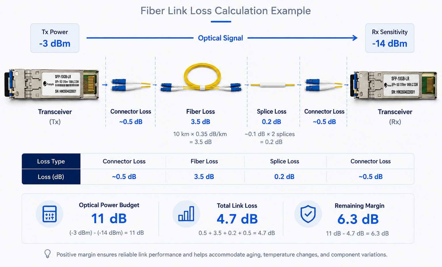
Consider a 10 km single-mode fiber link:
Fiber attenuation: 0.35 dB/km
Two connector pairs: 0.5 dB each
Two splices: 0.1 dB each
Fiber loss:
10 × 0.35 = 3.5 dB
Connector loss:
2 × 0.5 = 1.0 dB
Splice loss:
2 × 0.1 = 0.2 dB
Total estimated link loss:
3.5 + 1.0 + 0.2 = 4.7 dB
If the transceiver provides an 11 dB optical power budget, the theoretical remaining margin is:
11 - 4.7 = 6.3 dB
However, a practical fiber link should not be designed exactly at its maximum allowable loss.
Why Is Safety Margin Important?
Connector contamination, aging components, additional patching, temperature changes, and installation variations can increase optical loss over time.
Engineers therefore normally reserve several decibels of engineering margin. The appropriate value depends on the network architecture, equipment specifications, applicable standards, operating environment, and expected changes during the life of the link.
Don't Forget Receiver Overload
Low received power is not the only potential problem.
Every optical receiver also has a maximum input power specification. If link loss is too low, received optical power may exceed this limit and overload the receiver, potentially causing errors or unstable operation.
A proper link design should therefore verify that expected Rx power remains between the receiver sensitivity and maximum receiver input power specified for the transceiver.
Why Can a Link Fail Within the Rated Distance?
A module rated for 10 km does not guarantee that every link shorter than 10 km will operate correctly.
An 8 km link, for example, may include multiple connectors, patch panels, splices, or poor-quality fiber sections. If total insertion loss exceeds the available optical power budget, the received signal may still be too weak.
Optical power is also not the only limitation. On longer single-mode links, dispersion and other transmission impairments can limit reach even when received optical power is sufficient.
Using DOM/DDM to Check Link Conditions
After installation, DOM/DDM information can help engineers evaluate actual optical link conditions.
Rx optical power is particularly useful. If received power is lower than expected, possible causes include:
Dirty fiber connectors
Excessive fiber attenuation
Damaged or bent fiber cables
Unexpected connector or splice loss
Problems with the remote transmitter
DOM/DDM readings should always be compared with the specifications and thresholds of the actual optical transceiver.
Optical Power Budget vs Link Budget
Optical power budget generally describes the available optical loss between transmitter output and receiver sensitivity, while a complete link-budget calculation considers how that available power is consumed by fiber, connectors, splices, passive components, and engineering margin.
In practice, many manufacturers and technical documents use "optical power budget" and "link budget" interchangeably. Understanding the actual specifications and calculation method is therefore more important than the terminology itself.
Conclusion
Transmission distance alone is not enough to determine whether an optical transceiver will operate reliably.
A proper link assessment should consider optical power budget, fiber attenuation, connector and splice losses, receiver overload limits, and engineering margin. Longer links may also require consideration of dispersion and other transmission limitations.
By calculating link loss before deployment and checking actual Rx/Tx power through DOM/DDM after installation, engineers can identify potential problems more efficiently and build more reliable fiber links.
What Is an RJ45 SFP Module? A Guide to Copper SFP Transceivers
What Is DOM/DDM in Optical Transceivers and How Does It Help Troubleshooting?
Related Article