What Is DOM/DDM in Optical Transceivers and How Does It Help Troubleshooting?
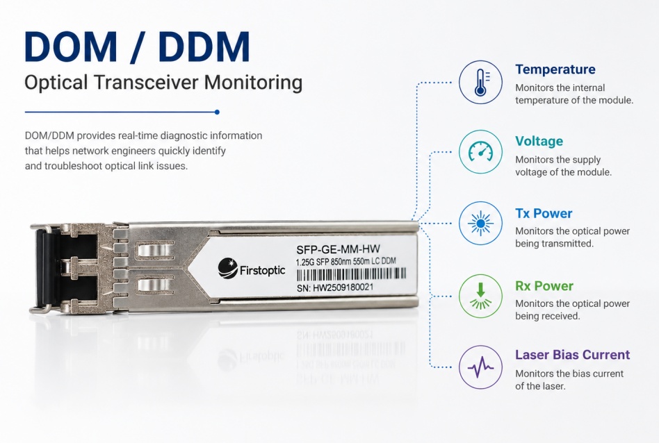
When an optical link becomes unstable or goes down, replacing the transceiver immediately is not always the best first step. Modern optical transceivers can often provide real-time operating information that helps network engineers identify where the problem may be occurring.
This capability is commonly known as DOM (Digital Optical Monitoring) or DDM (Digital Diagnostic Monitoring).
By monitoring parameters such as optical power, temperature, voltage, and laser bias current, DOM/DDM provides useful information about the operating condition of an optical transceiver and the fiber link.
What Are DOM and DDM?
DOM and DDM are commonly used to describe the diagnostic monitoring capabilities built into many optical transceivers.
Instead of only transmitting and receiving data, a supported transceiver can report real-time operating parameters to the host network device.
These values can then be viewed through the switch interface, network management system, or command-line tools supported by the equipment vendor.
DOM/DDM is widely available in modern SFP, SFP+, SFP28, QSFP+, QSFP28, and other optical transceiver families, although actual monitoring capabilities depend on the module and host device.
What Parameters Can DOM/DDM Monitor?
The most common diagnostic parameters include:
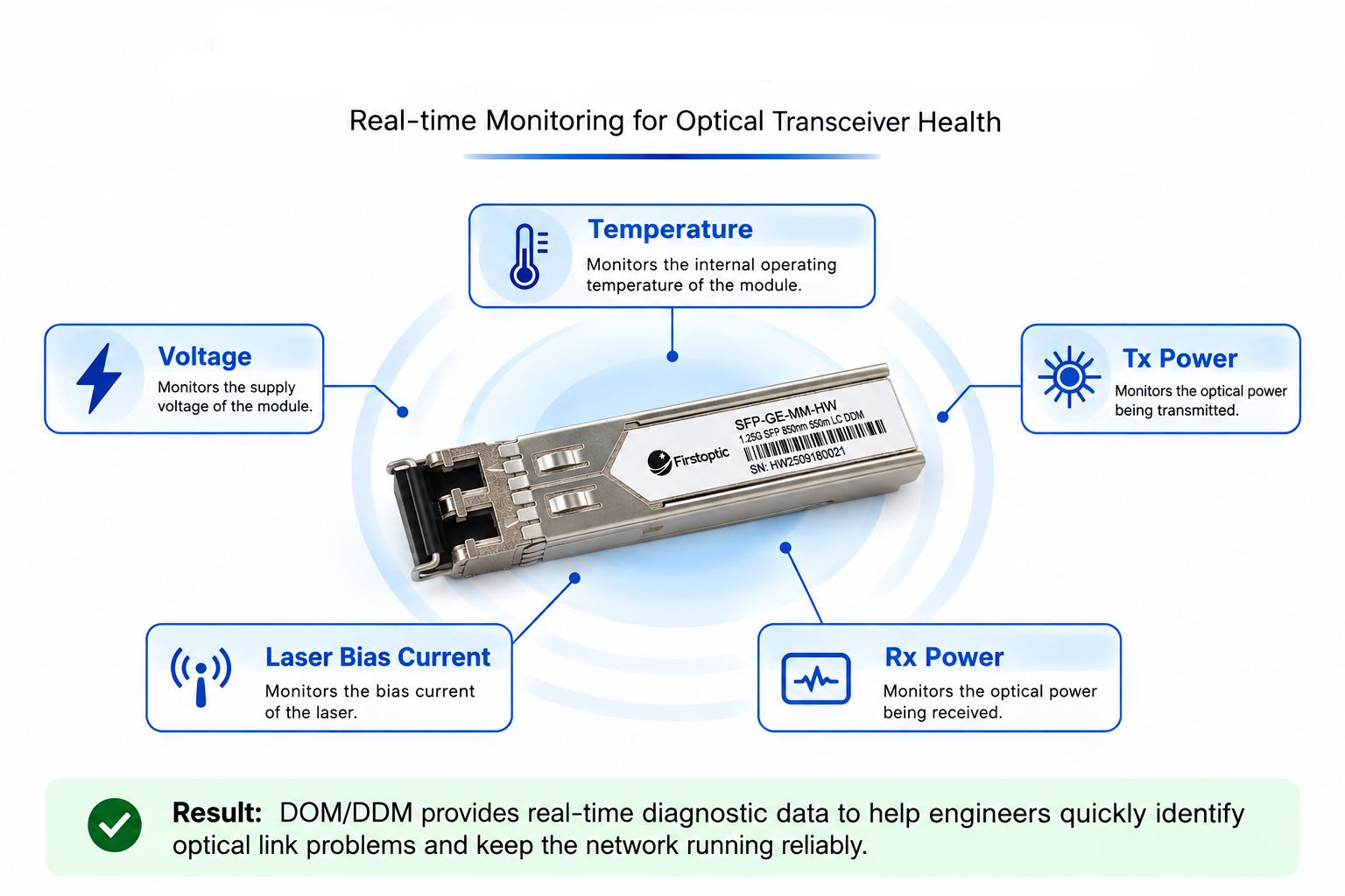
Temperature
Shows the internal operating temperature of the transceiver. Abnormally high temperatures may affect module performance or indicate cooling and airflow problems.
Supply Voltage
Monitors the voltage supplied to the module. Values outside the specified operating range may indicate a power or host equipment issue.
Tx Optical Power
Shows the optical power being transmitted by the module. An abnormal Tx value may indicate a transmitter or laser-related problem.
Rx Optical Power
Shows the optical power received from the remote end of the link. Low Rx power is particularly useful when diagnosing fiber attenuation, dirty connectors, excessive link loss, or other optical path problems.
Laser Bias Current
Indicates the electrical current used to drive the laser. Significant changes over time can provide additional information about transmitter operating conditions.
How to Read DOM/DDM Data
The most important point when reading DOM/DDM information is that there is no single optical power value that is correct for every transceiver.
For example, a 10G SR module and a 10G LR module use different optical technologies and have different Tx and Rx specifications. The acceptable values for a 100G module may also be different.
For this reason, DOM/DDM readings should always be compared with the operating thresholds specified in the transceiver datasheet.
A simplified diagnostic approach is:
Normal Tx + Low Rx
The local transmitter may be operating normally, while excessive loss exists somewhere in the optical path or at the remote end.
Abnormal Tx
The local transceiver, laser, host port, or power condition should be investigated.
High Temperature
Check equipment airflow, ambient temperature, port density, and cooling conditions.
Abnormal Voltage
Check the host device and power supply before assuming the optical module itself has failed.
How Does DOM/DDM Help Troubleshoot Optical Links?
DOM/DDM is useful because it helps narrow down the possible cause of a network problem before components are replaced.
Consider a link that suddenly goes down.
If the local module reports normal Tx power but very low Rx power, the problem may not be the local transceiver. Engineers can instead investigate the remote transmitter, fiber patch cable, connectors, or other sources of optical loss.
If both optical power readings appear normal but the link remains down, attention can shift toward other possible causes such as port configuration, speed mismatch, FEC settings, or transceiver compatibility.
DOM/DDM therefore does not replace troubleshooting. It provides additional evidence that helps make troubleshooting more efficient.
Common Causes of Abnormal DOM/DDM Readings
Abnormal diagnostic values do not automatically mean that a transceiver is defective.
Common causes can include:
Dirty or contaminated fiber connectors
Damaged or excessively bent fiber cables
Incorrect fiber type
Excessive transmission distance or link loss
Poor equipment airflow
Remote-side optical problems
Incorrect or incompatible network configuration
Cleaning and inspecting the fiber connection is often a useful first step when received optical power is unexpectedly low.
Does Every Optical Transceiver Support DOM/DDM?
Not necessarily.
DOM/DDM support depends on the transceiver design, standard, manufacturer, and host network equipment. Some devices may also support the module but provide limited access to diagnostic information.
Before relying on DOM/DDM, check both the optical transceiver specifications and the monitoring capabilities of the switch, router, or other host device.
Conclusion
DOM/DDM provides network engineers with valuable visibility into the operating condition of optical transceivers.
By monitoring Tx power, Rx power, temperature, voltage, and laser bias current, engineers can better distinguish between transceiver problems, fiber link issues, and other network conditions.
However, DOM/DDM values should never be interpreted in isolation. The readings should be compared with the specifications of the actual transceiver and considered together with fiber type, transmission distance, equipment configuration, and overall link conditions.
For modern optical networks, understanding DOM/DDM is a practical skill that can make optical link troubleshooting faster and more accurate.
Optical Power Budget Explained: How to Calculate Fiber Link Loss
From 100G to 400G: How PAM4 Changed Optical Networks
Related Article