400G DR4 Breakout: Choosing the Right 100G Optics
A 400G DR4 breakout link connects a supported 400G port to four separate 100G ports. The purchasing risk is assuming that any 100G module will work at the far end. Before choosing a harness, identify the optical interface required on each branch.
Start with the 100G Optical Signal
Each branch carries a single 100G PAM4 optical lane over single-mode fiber. A 100GBASE-DR module is designed for this type of connection. Check the interoperability documentation for the exact 400G and 100G part numbers.
Some implementations also support selected single-lambda FR1 or LR1 modules. That does not extend a standard DR4 link beyond its 500-meter reach. Use the supported distance and loss limits for the complete pairing.
Why an LC Connector Is Not Enough
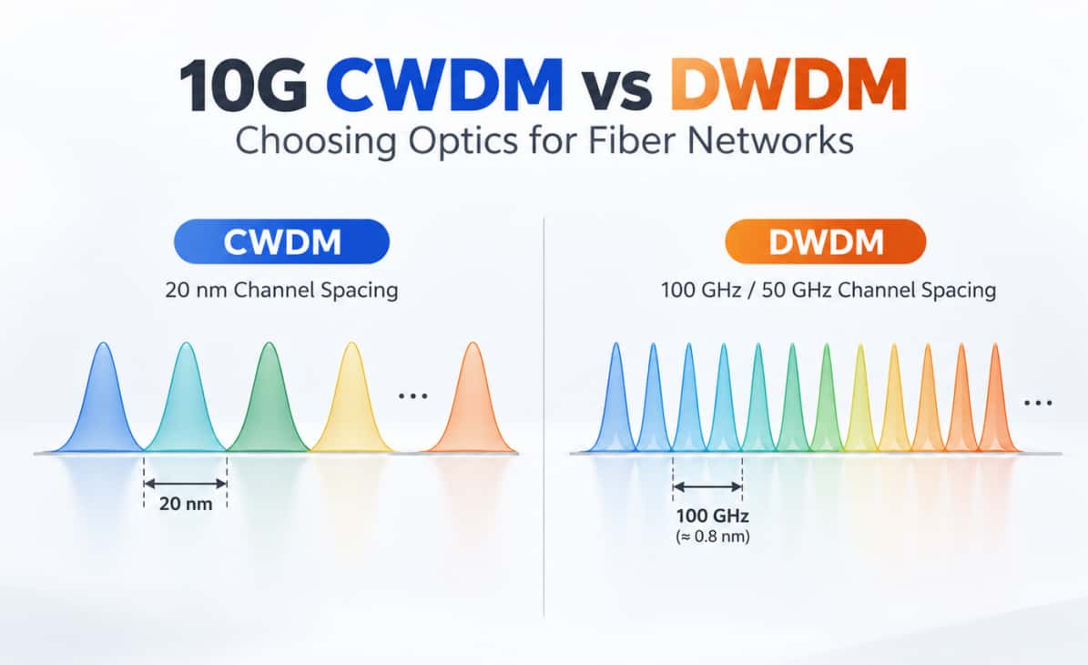
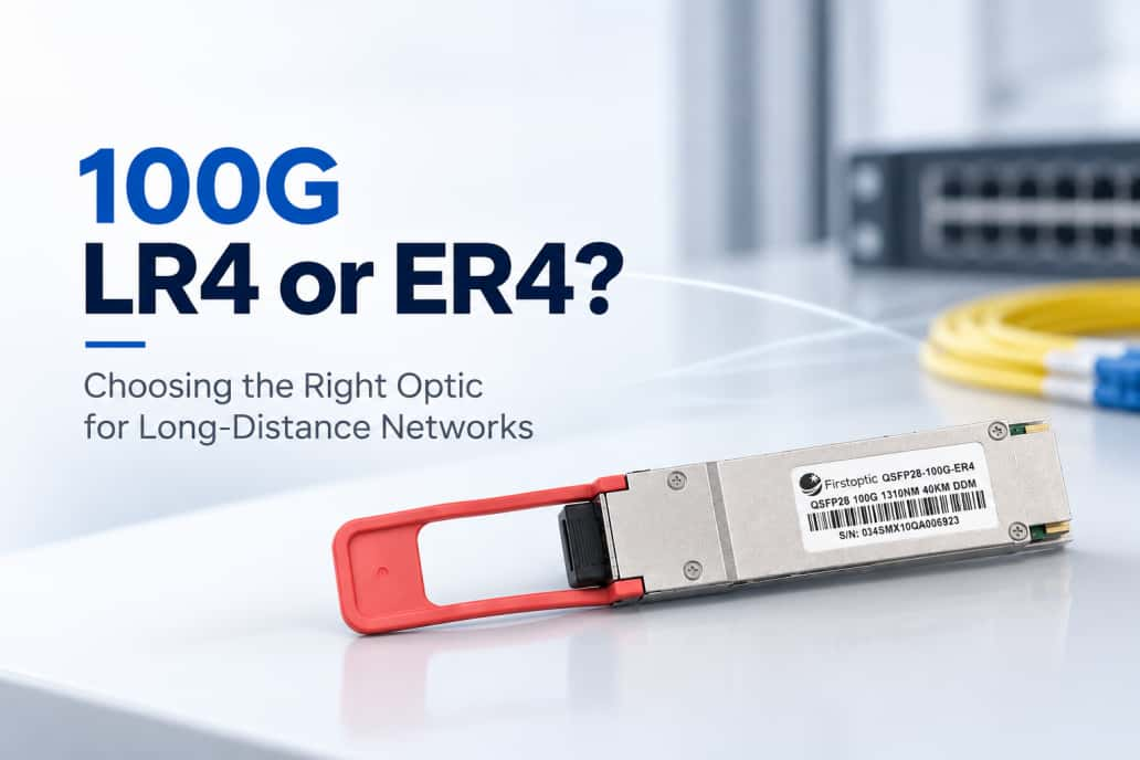
100G LR4 and CWDM4 modules also use duplex single-mode fiber, but combine four optical wavelengths into one 100G connection. They are not direct substitutes for the single-lambda 100G breakout optics required on a DR4 branch.
A passive harness routes fibers; it cannot convert modulation or wavelength architecture. Matching the connector shape, nominal speed or fiber category alone will not establish interoperability.
Check the Host Configuration
Before ordering 400G DR4 breakout components, record the switch model, line card, port number and software release. Confirm that this specific port supports four independent 100G interfaces with the selected module.
Then verify the required FEC settings at both ends. FEC may be handled differently by the host and the remote module. Follow the supported configuration rather than copying settings from another optical type.
Specify the Complete Fiber Path
For a module with an MPO-12/APC interface, select an OS2 breakout assembly that matches its active lanes and connector requirements. Verify MPO gender, end-face polish, transmit-to-receive mapping and the LC termination required by each remote optic.
Include patch panels, adapters and all connections when checking insertion loss. Label the four branches so that a failed path can be traced to its switch interface.
Build a Useful Purchase Request
List the 400G module, four remote 100G breakout optics, both host platforms, software versions, cable route length and complete connector configuration. Ask for confirmation of the whole combination.
After installation, validate all four interfaces individually. Record link state, negotiated configuration, error counters and traffic-test results before accepting the connection.
A successful 400G DR4 breakout deployment depends on matching the optical signal, host mode and fiber mapping. Choose the remote optics first, then confirm the cable assembly and configuration that connect the complete system.
Related Article