
From 100G to 400G: How PAM4 Changed Optical Networks
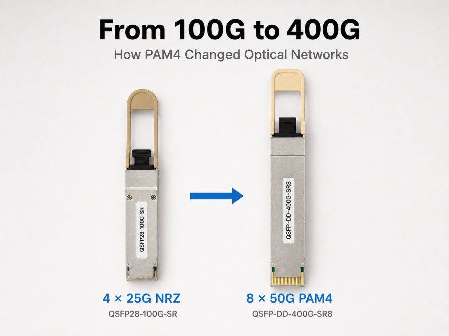
The transition from 100G to 400G is more than a simple increase in network speed. It represents an important change in signal modulation and lane architecture.
Traditional 100G networks commonly use four 25G lanes with NRZ signaling. To reach 400G without drastically increasing the number of ports and fibers, the industry adopted PAM4. This modulation technology carries more information within each symbol and enables significantly higher data rates per lane.
Why 100G Networks Need to Evolve
A typical 100G QSFP28 transceiver uses four 25G NRZ electrical lanes. This architecture has been widely deployed in data center spine-leaf networks, enterprise backbones and cloud infrastructure.
However, AI workloads, distributed storage and high-performance computing are creating much greater bandwidth requirements. Expanding capacity only by adding more 100G ports would require additional switches, fibers, rack space and power.
Next-generation networks therefore required a more efficient signaling scheme, and PAM4 emerged as the key technology to boost data throughput per lane.
NRZ and PAM4: What Is the Difference?
NRZ uses two signal levels to represent binary data. Each symbol carries one bit: either 0 or 1.
PAM4 uses four amplitude levels, allowing each symbol to represent two bits:
-
00
-
01
-
10
-
11
Because PAM4 carries two bits per symbol, it can transmit approximately twice as much information at a similar symbol rate compared with NRZ.
A lane operating at 53.125 GBaud carries a raw line rate of approximately 106.25 Gb/s using PAM4 signaling, supporting a nominal 100 Gb/s data rate after accounting for encoding and FEC overhead.
However, the tighter spacing between signal amplitude levels makes PAM4 more vulnerable to noise and channel loss compared with NRZ. PAM4 links therefore commonly use Forward Error Correction, equalization and digital signal processing to maintain reliable transmission.
This fundamental difference explains why PAM4 is essential for cost-effective 400G migration without drastically increasing fiber and port quantities.

How PAM4 Enables 400G Transmission
Traditional 100G QSFP28 modules commonly use four 25G NRZ electrical lanes. Many first-generation 400G QSFP-DD and OSFP modules use eight 50G PAM4 electrical lanes, providing a combined capacity of 400G.
The optical lane arrangement depends on the module type.
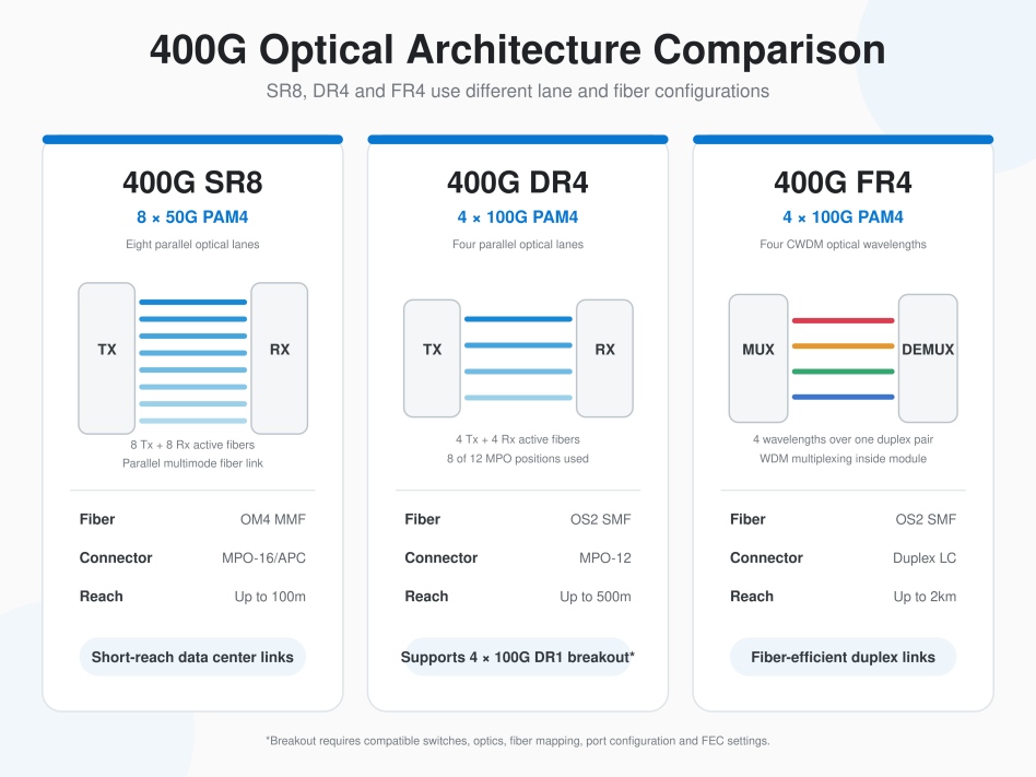
Some modules convert eight 50G electrical lanes into four 100G PAM4 optical lanes through an internal gearbox. This architecture is commonly used by 400G DR4 and 400G FR4 modules.
Other modules maintain eight 50G optical lanes. For example, 400G SR8 uses an 8 × 50G PAM4 optical architecture. It generally preserves the host-side lane count and does not require an 8-to-4 lane gearbox, although DSP may still be used for signal conditioning.
Electrical and optical lane counts are not always identical. The host interface, optical architecture and switch compatibility must therefore be checked separately.
Common 400G PAM4 Optical Architectures
Different 400G modules use PAM4 in different ways depending on the required fiber type and transmission distance.
400G SR8
400G SR8 uses eight 50G PAM4 optical lanes over parallel multimode fiber. It normally uses an MPO-16 connector and can support transmission distances of up to 100 metres over OM4 fiber.
SR8 is mainly designed for short-distance connections inside data centers.
400G DR4
400G DR4 uses four 100G PAM4 optical lanes over parallel single-mode fiber. It normally uses an MPO-12 connector with eight active fibers: four transmitting fibers and four receiving fibers.
400GBASE-DR4 supports distances of up to 500 metres. It can also support optical breakout to four independent 100GBASE-DR1 links, provided that the switch, transceivers, fiber mapping and port configuration support breakout mode, with compatible FEC settings across each link.
400G FR4
400G FR4 uses four 100G PAM4 optical lanes carried on four CWDM wavelengths.
The four wavelengths are multiplexed and demultiplexed inside the module, enabling 400G transmission over a single duplex fiber pair. FR4 normally uses a duplex LC connector and supports distances of up to 2 kilometres over single-mode fiber.
Unlike DR4, standard FR4 is not designed for direct optical breakout because its four optical lanes are multiplexed onto the same fiber pair.
Key Considerations for a 100G to 400G Upgrade
When planning a 100G to 400G network upgrade, operators should evaluate the complete link rather than considering only the transceiver speed.
Important factors include:
-
Switch port and form-factor compatibility
-
Electrical and optical lane architecture
-
Multimode or single-mode fiber infrastructure
-
Connector type and available fiber count
-
Required transmission distance
-
Breakout support and fiber mapping
-
Compatible FEC settings at both ends
For example, 400G DR4 is suitable when 4 × 100G DR1 breakout connectivity is required. FR4 is more appropriate when 400G must be transmitted over an existing duplex single-mode fiber pair. SR8 is commonly used for short-distance parallel multimode links.
Conclusion
PAM4 made the transition from 100G to 400G practical by increasing the amount of data carried by each lane. Instead of relying only on additional fibers and ports, network equipment can use 50G or 100G PAM4 lanes to achieve higher bandwidth with greater port density.
Understanding the relationship between PAM4, lane architecture and fiber infrastructure is essential when selecting between 400G SR8, DR4 and FR4 solutions.
HCH provides 400G QSFP-DD and OSFP optical transceivers for short-reach, parallel single-mode and duplex single-mode applications. Compatibility testing and module selection support are available for different switch platforms and network requirements.
What Is DOM/DDM in Optical Transceivers and How Does It Help Troubleshooting?
Why 25G Became the Building Block of 100G Data Center Networks
Related Article


