What Is FEC in Optical Networking, and Why Does It Matter?

As Ethernet networks move from 10G and 25G to 100G, 200G and 400G, maintaining signal integrity becomes increasingly important. Higher data rates introduce tighter signal margins, making error correction essential for many high-speed Ethernet interfaces.
Forward Error Correction (FEC) helps receivers recover data affected by transmission errors. However, an incorrect FEC configuration can also prevent an optical link from operating correctly.
Understanding FEC is important for network engineers working with high-speed optical transceivers, switch ports and Ethernet link troubleshooting.
What Is FEC and How Does It Work?
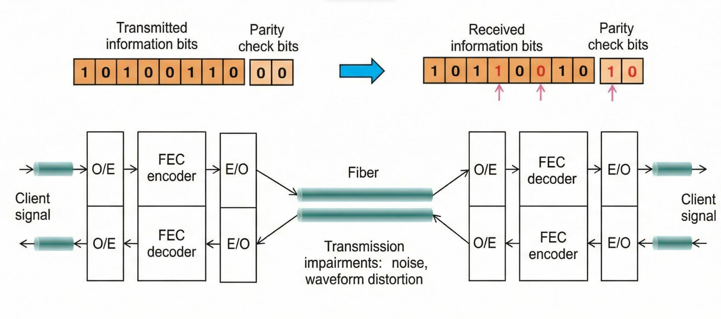
Forward Error Correction adds redundant information to transmitted data, allowing the receiver to detect and correct certain errors without requesting retransmission.
Before transmission, an encoder processes the data and adds error-correction information. At the receiving end, the decoder uses this information to recover data affected by errors within the code's correction capability.
This improves link reliability when the physical signal experiences a limited number of transmission errors.
However, FEC cannot repair damaged fiber, eliminate excessive optical loss or correct an unlimited number of errors. If signal quality falls beyond the correction capability, uncorrectable errors may still occur.
Why High-Speed Ethernet Needs FEC
Many modern high-speed Ethernet interfaces use PAM4 signaling, which represents two bits per symbol using four amplitude levels.
Compared with NRZ signaling, PAM4 operates with smaller separation between signal levels for a comparable signal swing. This makes the signal more sensitive to noise and distortion.
FEC helps manage transmission errors that may occur under these conditions.
For many 100G, 200G and 400G Ethernet interfaces, error correction is an integral part of the specified physical-layer operation.
However, the required FEC scheme depends on the applicable Ethernet PHY standard and port operating mode. It cannot be determined solely from the transceiver's advertised data rate.
Common FEC Modes in Ethernet Networks
Different Ethernet interfaces use different error-correction schemes.
| FEC mode | Description | Typical application |
|---|---|---|
| No FEC | Operates without forward error correction | Interfaces that do not require FEC |
| BASE-R FEC | Firecode-based error correction | Certain 25G Ethernet PHYs |
| RS-FEC | Reed-Solomon error correction | Certain 25G and many higher-speed Ethernet PHYs |
These modes are not interchangeable across all optical interfaces.
For example, RS-FEC includes different code configurations, and some Ethernet PHYs require a specific FEC scheme rather than allowing the user to select freely.
Switches may also provide different FEC options depending on the port speed, breakout configuration and supported interface type.
The correct mode should therefore be confirmed using the switch documentation and the applicable Ethernet specification.
Can FEC Mismatch Cause Link Failure?
Yes. Incompatible FEC configurations can prevent a high-speed Ethernet link from establishing or cause unstable operation.
For example, a switch may successfully recognize a 100G or 400G optical transceiver while the Ethernet interface remains down.
This happens because detecting a module through its management interface does not mean the physical Ethernet link has established successfully.
If the connected ports use incompatible PHY modes or FEC requirements, the link may fail even when the optical modules are recognized.
However, FEC is only one possible cause. Incorrect port settings, unsupported optical interfaces and physical signal problems can produce similar symptoms.
Engineers should verify the required PHY mode and FEC configuration before assuming that the transceiver itself is defective.
How to Verify FEC Settings During Troubleshooting
When a high-speed optical link fails or becomes unstable, a structured troubleshooting process can help identify whether error correction is involved.
1. Confirm the port operating mode.
Check that both switches support the required Ethernet speed, PHY type and interface configuration. If breakout is enabled, verify the supported mode on both ends.
2. Check FEC settings on both devices.
Use the switch's interface commands or management software to review the configured and operational FEC modes. Compare them with the requirements of the selected Ethernet interface.
3. Review FEC error counters.
Two commonly reported indicators are:
-
Corrected errors: Errors successfully recovered by the FEC decoder. A rising counter does not automatically indicate link failure; the error rate and operating conditions matter.
-
Uncorrectable errors: Errors that exceed the correction capability. Persistent increases can indicate a physical-layer problem requiring further investigation.
4. Examine optical diagnostics.
Where supported, check transmitted and received optical power, module temperature and other diagnostic information.
Optical power within the specified range does not guarantee that every signal-quality requirement is satisfied, so these readings should be considered alongside FEC and interface counters.
5. Apply only supported FEC configurations.
Follow the switch vendor's documentation and the relevant Ethernet standard. Do not disable FEC on an interface that requires it.
After making a supported configuration change, verify that the link remains stable and monitor error counters over time.
Key Takeaways
Forward Error Correction improves high-speed Ethernet reliability by correcting certain transmission errors before they affect received data.
For 100G, 200G and 400G optical networks, FEC requirements depend on the Ethernet PHY and port configuration, not simply on the optical transceiver's speed.
When a module is recognized but the link remains down, checking FEC compatibility alongside interface settings and physical-layer diagnostics can help identify the cause.
Understanding these requirements helps network engineers deploy optical transceivers more reliably and avoid unnecessary module replacements.
Related Article