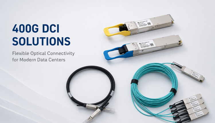
HCH - Introduces You To Optical Modules
2024-09-27
1、The Working Principle Of the Optical Module
Optical Modules, as an important part of optical fiber communication, are optoelectronic devices that realize the functions of photoelectric conversion and electro-optical conversion in the process of optical signal transmission.
Optical module works in the physical layer of OSI model and is one of the core devices in optical fiber communication system. It is mainly composed of optoelectronic devices (optical transmitter, optical receiver), functional circuits and optical interfaces, and its main role is to achieve photoelectric conversion and electro-optical conversion functions in optical fiber communication.
The sending interface input a certain bit rate electrical signal, after the internal driver chip processing by the driving semiconductor laser (LD) or light emitting diode (LED) to emit the corresponding rate of modulation optical signal, after transmission through the optical fiber, the receiving interface and then the optical signal is converted by the optical detection diode into an electrical signal, and after the preamplifier output the corresponding bit rate electrical signal.

Figure1:Working principle of the optical module
2、Appearance Of An Optical Module
There are many kinds of optical modules, and their appearance and structure are not the same, but their basic composition structure contains the following parts, as shown in Figure 2.

Figure2:Appearance of the optical module (SFP package as an example)
Table1-1 Describes the structures of optical modules
|
Structure
|
Instructions
|
|
1.Dust-proof cap
|
Protect optical fiber connectors, optical adapters, optical interfaces of optical modules, and ports of other devices from external pollution and damage.
|
|
2.Petticoat
|
It is used to ensure good bonding between the optical module and the optical interface of the device, and only exists on the optical module of the SFP package.
|
|
3.Tag
|
This parameter is used to identify key optical module parameters and manufacturer information.
|
|
4.Splice
|
Used to connect optical modules and boards, transmit signals, and supply power to optical modules.
|
|
5.Shell
|
Protect internal components, there are mainly 1*9 shell and SFP shell two.
|
|
6.Receiving interface (Rx)
|
Optical fiber receiving interface.
|
|
7.Send Interface (Tx)
|
Optical fiber sending port.
|
|
8.Pull fastener
|
It is used for removing and inserting optical modules. In order to facilitate identification, the color of the handle corresponding to different bands is also different.
|
3、Common Categories Of Optical Modules
3.1 Classification by rate
In order to meet the needs of various transmission rates, optical modules with different speeds have been produced: 52M, 155M, 622M, 1.25G, 2.5G, 3G, 4.25G, 8.5G, 10G, 16G, 25G, 40G, 100G, 400G, etc. (Shannon's Theorem).
3.2 Classified by package type
The higher the transmission rate, the more complex the structure, resulting in different packaging methods: 1x9, GBIC, SFF, SFP, eSFP, CX4/Xenpak/X2, XFP, SFP+, CFP, QSFP+, CFP2, QSFP28, CFP4, CFP8 and so on.
3.3 Classification by pattern
Optical fibers are divided into single-mode fiber and multi-mode fiber. In order to use different types of optical fibers, single-mode optical modules and multi-mode optical modules are produced.
The central wavelength of the single-mode optical module is generally 1310nm and 1550nm, which is used with single-mode optical fibers. Single-mode optical fiber has wide transmission frequency band and large transmission capacity, which is suitable for long distance transmission.
The central wavelength of the multi-mode optical module is generally 850nm, which is used with multi-mode optical fibers. Multi-mode fiber has mode dispersion defect, its transmission performance is worse than that of single-mode fiber, but the cost is low, and it is suitable for small capacity and short distance transmission.
★Note: If a long-distance optical module is used, the sending optical power is generally greater than the overload optical power. Therefore, pay attention to the optical fiber length to ensure that the actual receiving optical power is smaller than the overload optical power. If the length of the optical fiber is short, use the long-distance optical module with the optical fiber attenuation (the attenuation value per unit length of the optical fiber, in dB/km) to avoid burning the peer optical module.

Figure3:Classification diagram of optical modules
4、Indicator Performance Of Optical Module
4.1 Output optical Power :Tx Power
Output optical power of the light source at the sending end of the optical module (unit :dBm). (Pavg, Poma, dBm and mW)
4.2 Receiving Sensitivity :Rx Sensitivity
The minimum received optical power of the optical module at a certain speed and bit error rate, in dBm(milliwatt decibels). In general, the higher the speed, the worse the sensitivity. (Pressure sensitivity, light saturation)
4.3 Transmission distance:
Light is lossy when it travels through optical fibers. The transmission distance of the optical module is determined by the output optical power, the receiving sensitivity and the transmission attenuation on the optical path.
4.4 Other indicators:
Transmission rate, Eye-Margin, extinction ratio ER, spectral width, edge mode rejection ratio SMSR, Jitter Jitter, channel cost DP, optical link budget, optical power loss at different wavelengths, etc.
5、Application Of Optical Module
Application environment: In the field of communication data centers, high-performance computers/supercomputers, storage networks, access networks, power grids, power systems, MAN, and in the security, rail transit, energy and chemical industry, aerospace, unmanned and other fields are also used.
Equipment/modules: switches, routers, optical transceivers, network cards, optical backplanes, etc.
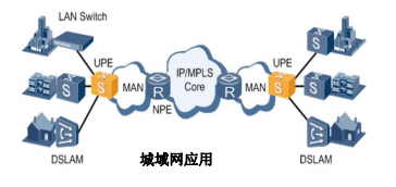

Figure4:Application diagram of optical module
Three typical applications of CWDM/DWDM: metro ring topology, point-to-point fiber expansion, point-to-multipoint topology.


Figure5:Schematic diagram of three typical applications of CWDM/DWDM
6、The Optical Module Is Easy To Locate
6.1 Test whether the optical power is within the range required by the indicator. If no light or low optical power occurs.
Treatment method:
A. check the optical power selected wavelength and measurement unit (dBm).
B. Clean the end faces of the optical connectors and the optical ports on the optical modules.
C. check whether the optical fiber connector end face is black and scratched, whether the optical fiber connector is broken, replace the optical fiber connector for interchangeability test.
D. Check whether the optical fiber connector is slightly bent.
E. The hot-swappable optical module can be reinserted for test.
F. Replace an optical module on the same port or replace a port on the same optical module.
6.2 If the optical power is normal but the link fails, check the 1ink indicator and extract the following information:
A. Login information of the optical module on the device
B. Read the basic information and DDM information of the optical module through the switch control port
C. Switch logs (mainly trapbuffer and logbuffer)
★Device information, optical module information, and basic networking information are necessary information
Statement: Quality content is to share with you, some articles from the network, if there is infringement please inform us, we will deal with it in the first time.
Do you know which devices optical modules are applied to?
HCH Tech delivers 10G XFP transceive
Related Article
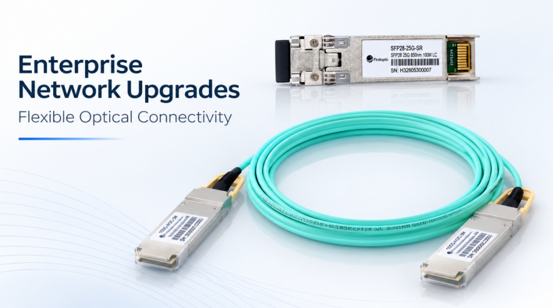
HCH provides flexible optical connectivity solutions to support enterprise network upgrades, including SFP, SFP28, QSFP28, AOC, and DAC solutions for different network requirements.
HCH Supports Enterprise Network Upgrades with Flexible Optical Connectivity Solutions
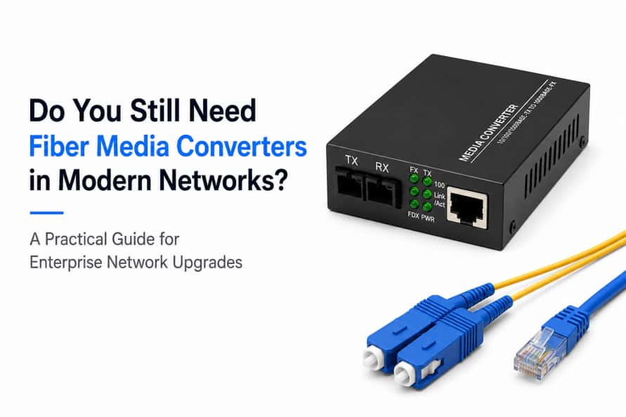
Learn why fiber media converters are still widely used in modern networks, when they are the right choice, and how they compare with fiber switches.
Do You Still Need Fiber Media Converters in Modern Networks?